
The LED flashing frequency mainly depends on the R1 & C1 values. In this circuit, a resistor with 390 ohms is mainly used to restrict the flow of current throughout the transistor & the LED. This circuit works like an oscillator using a resistor -10K and a capacitor – 100uF. This transistor includes three pins like bases-2 & emitter-1. This circuit can be built with a 2N2646 transistor which is a PN UJT. The required components to build this circuit are a 9V to 12V battery, 2N2646 UJT, LED, 10KΩ & 390Ω resistors, breadboard, and connecting wires.

The circuit diagram of the LED flasher using the 2N2646 unijunction transistor is shown below.
#Qucs unijunction transistor oscillator how to#
How to use 2N2646 Uni Junction Transistor? As a result, throughout the beginning period, the voltage drop of UJT will be equivalent to VCC. Once the power is turned ON, then the uni-junction transistor will activate to high resistance condition & whole voltage supply come into view across it.
The surface is passivated for uniformity & reliability. The typical low emitter reverse current is 0.005♚ (Typ). Accessible like Sn/Pb plating (non-RoHS). The range of operating temperature is -65✬ to +150✬. Emitter reverse voltage Max (VB2E) is 30V. The maximum two bases voltage (VB2B1) is 35V. The features and specifications of the 2N2646 Uni Junction Transistor include the following. Pin4 (Case): This pin is connected internally to the base2 pin. Pin3 (Base 2): This pin is connected normally to Load. Pin2 (Emitter): This pin is used to turn ON/OFF the transistor. Pin1 (Base 1): This pin is connected normally to power. This transistor includes three terminals which are discussed below. The pin configuration of a 2N2646 Uni junction transistor is shown below. So it is very useful for oscillator circuits. So, this resistance drop will make the UJT operate above negative resistance. So this resistance drop will make the emitter terminal connect in forwarding bias so that the current will be injected more. This extra current on the base region permits the resistance among emitter (E) & B2 which leads to reduction therefore the conductivity of the UJT improves. The current will flow from the emitter terminal to the base, once the voltage of the emitter is increased one diode voltage over the voltage wherever P-type material diffusion occurs. Once the positive supply is given to the two base terminals of this transistor then a potential drop will occur. This transistor can also be used as an oscillator because it exhibits negative resistance. Once this transistor is turned ON then it permits the emitter current to enhance until it is restricted through the power supply in the emitter terminal. Working of 2N2646 Uni Junction Transistor This transistor generally works once the emitter junction is connected in forwarding bias whereas the JFET functions normally whenever the gate terminal is connected in reversed bias. The UJT structure & N-Type JFET is quite similar, however, the surface of the gate terminal within N-Type JFET is larger as compared to the emitter junction within UJT. But, if the huge voltage is given at the emitter (E) terminal then large current will supply from two base terminals like B1 to B2 so that it will generate huge B2 o/p current. The emitter (E) is closed to base terminal B2 than base terminal B1, then this device doesn’t include a symmetrical construction but some amount of current will be supplies through B1 to B2 whenever there is no potential dissimilarity between two terminals like E & B. 
Once the emitter terminal behaves like an open-circuit, then the resistance between two base terminals (B1 & B2) is known as inter-base resistance. This device mainly depends on the formation of a single junction among two materials like p-type & n-type.

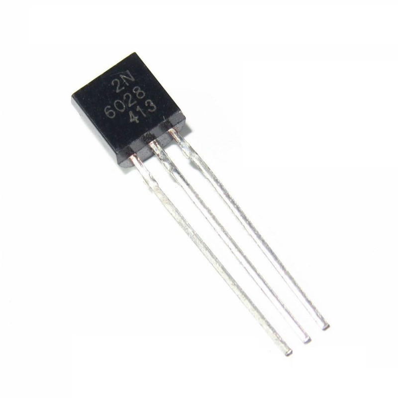
In this transistor, the base terminal is composed of n-type silicon which is lightly doped whereas the emitter terminal is doped heavily & includes p-type material. Typical 2n2646 UJT includes three terminals like emitter, base & collector. This transistor is composed of n-type semiconductors wherever p-type material is fixed with its length to assist in fixing the intrinsic standoff ratio parameter (η). This UJT or uni-junction transistor cannot be used as a linear amplifier however it is widely used in triggered oscillators, free-running oscillators, and pulse generation circuits of low frequencies. 2n2646 UJT transistor is a 3-terminal semiconductor device that contains only one junction & it behaves like an electrically controlled switch.


 0 kommentar(er)
